Mechanical Clock
Building a mechanical clock completely from stock material using manual machine tools. This project is ongoing.
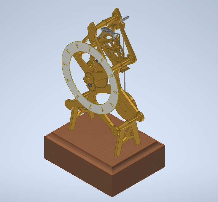
Building a mechanical clock completely from stock material using manual machine tools. This project is ongoing.
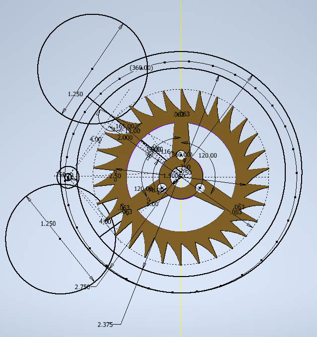
The escape wheel is the defining mechanism of a mechanical clock.
It simultaneously tracks the isochronic swing of the pendulum, translating the swing into the
motion of the clock hands, and provides additional energy to the pendulum with every swing to
keep it moving.
A recoil escapement was chosen for it's relative simplicity and forgiving
nature. To design the escape wheel, I followed the British Horological Institute's guide that
has been the same for nearly 100 years. The layout for the final escape wheel is shown on the
left.
After completing the bulk of the design, it seemed that the most
challenging part of the clock manufacture would be the gears (called wheels for the larger
driving gear and pinions for the smaller driven gear). One trait of mechanical clocks that is
uncommon in the modern world is that the large gear is usually driving the small gear. Because
of this, the obsolete cycloidal tooth form is more optimal than the modern involute gear form.
The mesh efficiency of gears is particularly important when you desire a clock to run on a
single wind for a week or more. This is all to say that gear cutters for the necessary gears are
not available for any reasonable price off the shelf.
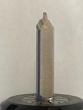
So, as a proof that the clock could
be manufactured, the first part to be made was the gear cutter pictured to the left. The profile
approximates the inverse of the involute tooth form and the necessary angular geometries are
machined into the tool steel before it is hardened to actually cut gears. This is my next step.